Thursday, October 30, 2008

'Useful To Know' Commands


I have created this post to document all those ad hoc commands that can be extremely useful but can also be easily forgotten! Plus its these little tweeks that CCIE labs love to drop into the mix. Over time i hope this grows, and pls let me know if you have any suggestions of your own.

show tcp brief
Shows the status of tcp sessions on the router. Useful for troubleshooting.

ip pim spt-threshold infinity
By default PIM sparse mode will automatically move over to a source tree topology once the source has been discovered via the shared tree. This command can be used to disable this default behaviour.

ip tcp syn-timeout 5
Reduces the time the IOS will wait for a TCP SYN-ACK before timing out and returning control to the command prompt. Can be usefull if you've ever waited around for control to return after a failed telnet session attempt!

configuration mode exclusive auto
Once conf t mode is entered an exclusive lock is applied to prevent other users entering conf t.

ppp reliable-link
ppp reliable link is Cisco's implementation of RFC 1663:PPP Reliable Transmission. It enables negotiation and use Numbered Mode LAPB over a serial link. This effectively ensures retransmissions if packet loss or error is detected.

vlan dot1q tag native
By default a dot1q trunk will leave the native VLAN untagged. Use this command to ensure all VLANs are tagged with a 32 bit header

show ip bgp neighbor {address} inc Flags
Flags: higher precedence, nagle, md5
This command will denote whether BGP encryption is in use with the denoted peer.

logging trap {n}
Used to specify the severity of log messages that generate traps.

transport preferred none
The default ios behaviour when typing an ip address (or anyother name) and hitting enter assumes the user is attempting a start a telnet session. This can be changed! with this command. Once entered the user has to be explicit when trying to start a telnet session i.e. telnet {address}.

ipv6 rip {name} default-nformation originate
ipv6 rip {name} default-information only
The first command, as you might expect, injects a default route. The second command injects a default route and filters all other more specific routes.

show queue {interface}
Input queue: 0/75/0/0 (size/max/drops/flushes); Total output drops: 0
Queueing strategy: Class-based queueing
Output queue: 0/1000/64/0 (size/max total/threshold/drops)
Conversations 0/1/256 (active/max active/max total)
Reserved Conversations 0/0 (allocated/max allocated)
Available Bandwidth 772 kilobits/sec

This command shows the amount of available bandwidth left on an interface for allocation via a service policy.

class-map {xxxx}
match not protocol {yyyy}
Allows a class map to match all protocols except the one specified

int {x}
switchport trunk encap dot1q
switchport mode trunk
switchport nonegotiate
This config enables trunking on the specified interface. Even though 'trunking' mode has been specified the port will still issue DTP frames. The 'nonegotiate' ensures DTP frames are not issued. Conversely 'switchport mode dynamic desirable' can be used to enable DTP.

priority x y
When configuring a priority this goes hand in hand with setting the max available bandwidth x. Another option 'y' allows the burst value to be set.


router bgp x
no bgp fast-external-fallover

neighbor {a.b.c.d} timers 10 30
To ensure bgp routes are not immediately withdrawn from the table when a directly connected link to a neighbor drops the above commands can be used. In this instance the link is only declared down once an hello has not been received for 30 seconds.

service timestamps log datetime msec
adds current date and time including the milliseconds to logging messages

ignore lsa mospf
Cisco routers do not support LSA Type 6 MOSPF packets. Use this command to suppress warning messages if they are received.

ip ospf authentication null
Use this command to turn off authentication on an interface. N.B. Do not use no ip ospf authentication!! This will not work.

ip hello-interval eigrp x y
ip hold-time eigrp x z
To adjust the EIGRP timers use the above commands under the interface configuration. IMO it would have been a more congruent design to have had 'ip eigrp hello-interval/hold-time'. Take a look at 'ip ospf hello-interval' for example! But i guess its not my place to reason why, just to make a mental note for when i'm searching for the command and wondering where it has gone:-)


ip multicast rpf backoff x y
Command to alter the frequency of triggered RPF checks. Usefull when there is unstability in the unicast routing table. x = minimum in ms and y = maximum in ms.

line vty 0 4
ipv6 access-class
To apply an ipv6 access-class under the vty interface prefix with ipv6.

ip ftp username ric
ip ftp password cisco

With the commands above the router is configured to use the username "ric" and the password "cisco" for FTP connections.

show ntp ass det
150.1.1.1 configured, authenticated, our_master, sane, valid, stratum 8
Usefull command to determine if the ntp connection is authenticated.

line vty 0 4
rotary 23

Enables the telnet service on port 3023 (in addition to port 23). Honest! i've tried it:-)

show ip port
I stumbled across this one by accident when trying to determine listening sockets on a router (show have use ship ip scoket). This command is fantastic if you want to list the IANA ports and the relevant protocols. Could be very usefull when building acls and class maps.

config-if#ip nbar protocol-discovery
show ip nbar protocol-discovery
Wow. Stumbled across this one on a lab. It keeps a record of all the protocols flowing through a port.

logging rate-limit n
Limit the number of syslog messages to n per second

logging rate-limit n except x
limit the number of syslog messages to n pers second except for those of priority x and higher

line vty 0 4
refuse-message @Try in 5 mins@
Configure a message when the connection is refused e.g. when all lines are busy

Wednesday, October 29, 2008

ip alias

How can you make a device 'own' an address when it has no interfaces with that address??!! An example where this could theoretically be a requirement is where some hosts have been configurd with an incorrect host entry i.e. with the wrong ip address specified for the host.

With the ip alias command this effectivelly allows multiple addresses to be assigned to the router.

With the following command the router will respond to a telnet session to ip address 1.1.1.1

ip alias 1.1.1.1 23

use the command show ip alias to verify

CISCO menu

In my previous post CISCO IOS privilege levels i denoted how user access to specific commands can be controlled by making use of CISCO privilege levels. Another tool available in the CISCO arsenal is the use of menus.

By making use of the menu command access can be limited to the commands explicitly made available on the menu only.

To apply menu access to a particular user login simply apply the following config where RICH is the name of the menu to be invoked upon login.

user x password y
user z autocommand menu RICH

line vty 0 4
login local


Unless configuring menus is something that you do day to day, or you have a desire to master this subject my thoughts on creating the menus is to refer to the CISCO doc cd and crib the syntax from there.

http://www.cisco.com/en/US/docs/ios/12_2/configfun/configuration/guide/fcf004.html#wp1002212

The example given is


menu new title ^C
Telnet Menu
^C
menu new prompt ^C
Please enter your selection: ^C
menu new text 1 telnet system1
menu new command 1 telnet system1
menu new options 1 pause
menu new text 2 telnet system2
menu new command 2 telnet system2
menu new options 2 pause
menu new text b telnet systemblue
menu new command b telnet systemblue
menu new options b pause
menu new text me show user
menu new command me show user
menu new options me pause
menu new command here show version
menu new text Exit Exit
menu new command Exit menu-exit
menu new clear-screen
menu new status-line
menu new default me

Invoking the above config gives the following menu

C
Telnet Menu


1 telnet system1

2 telnet system2

b telnet systemblue

me show user

Exit Exit

C


One hidden command 'show version' is available in this menu. This can be invoked by entering the text 'here'.

One point on this doc cd example i didnt like was the Exit command. Once entered it returns the user to the command prompt! In a real world scenario i would suggest this needs to be changed to exit the router.

This leads me to another point. After applying the following config.....

no menu new command Exit menu-exit
menu new command Exit exit

I found the first command no menu new command Exit menu-exit had in fact removed the whole menu! Hence before attempting any mods on a menu save in notepad first! Once reapplying the config with this modified command it had the desired effect - upon exiting the menu the users telnet session is terminated.

Monday, October 27, 2008

WRED - Part I precedence based

The TCP algorithm by default will cause TCP senders to back off when packet loss occurs. One of the main problems with this is that all senders will back off at the same time and slowly build up the transmission rate until packet loss occurs again. Much like cars on a three lane motorway this causes the 'concertina effect' where all traffic backs off and speeds up at the same rate.

The aim of WRED or Weighted Random Early Detect is to get around this problem by intelligently getting senders to back off at different times based on the configured weightings.

To enable the default WRED algorithim simply requires the config-if#random-detect parameter to be entered on the required interface.

The default settings can be viewed with the show queueing random-detect command.

R1#s queueing random-detect
Current random-detect configuration:
FastEthernet0/0
Queueing strategy: random early detection (WRED)
Random-detect not active on the dialer
Exp-weight-constant: 9 (1/512)
Mean queue depth: 0

class Random drop Tail drop Minimum Maximum Mark
pkts/bytes pkts/bytes thresh thresh prob
0 0/0 0/0 20 40 1/10
1 0/0 0/0 22 40 1/10
2 0/0 0/0 24 40 1/10
3 0/0 0/0 26 40 1/10
4 0/0 0/0 28 40 1/10
5 0/0 0/0 31 40 1/10
6 0/0 0/0 33 40 1/10
7 0/0 0/0 35 40 1/10
rsvp 0/0 0/0 37 40 1/10


Of note in the above output:-

class 0 -7 : denotes the IP precedence value.
tail drop pkts Min: denotes the interface queue size at which packets will start to be dropped.
tail drop pkts Max: denotes the interface queue size at which all packets will be dropped.
Mark Prob: denotes the fraction of packets that will be dropped once the tail drop pkts Min has been reached. The default being 1 in 10.

If there was a lab requirement to ensure packets with an ip precedence of 0 (routine) were to be subject to tail drop when the interface queue size reached 10 (as opposed to the default of 22) this can be achieved as follows:

int fa0/0
randon-detect precedence 0 10 40 10


Once entered the new parameter settings can be viewed by using the show queueing random-detect command again.

R1#s queueing random-detect
Current random-detect configuration:
FastEthernet0/0
Queueing strategy: random early detection (WRED)
Random-detect not active on the dialer
Exp-weight-constant: 9 (1/512)
Mean queue depth: 0

class Random drop Tail drop Minimum Maximum Mark
pkts/bytes pkts/bytes thresh thresh prob
0 0/0 0/0 10 40 1/10
1 0/0 0/0 22 40 1/10
2 0/0 0/0 24 40 1/10
3 0/0 0/0 26 40 1/10
4 0/0 0/0 28 40 1/10
5 0/0 0/0 31 40 1/10
6 0/0 0/0 33 40 1/10
7 0/0 0/0 35 40 1/10
rsvp 0/0 0/0 37 40 1/10

WRED can also be enabled based on DSCP settings and also based on configured traffic classed. Food for another post.

Sunday, October 26, 2008

Multicast Routing - Part IV Limiting Bandwith Part 2

In my previous post on rate limiting multicast traffic i made use of the ip multicast rate-limit function. If prohibited from using the function similar limiting can be achieved via MQC. As ever with the CCIE lab i think it pays to have more than one method of achieving the same goal.

ip access-list extended MCAST
permit ip 224.0.0.0 31.255.255.255

class-map MCAST
match access-group name MCAST

policy-map LIMITMCAST
class MCAST
police 8000

interface s2/0
service-policy output LIMITMCAST


R2#show policy int s2/0

Serial2/0

Service-policy output: S2/0

Class-map: LIMITMCAST (match-all)
7450 packets, 3340440 bytes
5 minute offered rate 0 bps, drop rate 0 bps
Match: access-group name MCAST
police:
cir 8000 bps, bc 1500 bytes
conformed 5089 packets, 1649908 bytes; actions:
transmit
exceeded 2173 packets, 1679628 bytes; actions:
drop
conformed 0 bps, exceed 0 bps

Class-map: class-default (match-any)
991 packets, 47636 bytes
5 minute offered rate 0 bps, drop rate 0 bps
Match: any

Friday, October 24, 2008

OSPF routing part VI - load balancing


Consider the scenario where router 4 and 5 are running OSPF and have 2 paths connecting each other: one over a 1.544 mb frame relay connection and the other a 100MB LAN segment.

The requirement here is to get OSPF to equally load balance traffic over both connections, but without adjusting the OSPF cost.

The OSPF default is that it will load balance over 4 paths as long as they have equal cost. In this scneraio the OSPF cost can be examined using the show ip ospf interface command. The Frame-relay cost is 64 and the LAN segment has cost 1. This is calculated by dividing the auto-cost reference bandwidth ( 100,000,000 ) by the interface bandwidth.

Herein lies the clue to enable resolution of this problem. If we are prohibited from adjusting the cost, the only other variable that can be used to influence OSPF is the interface bandwidth. This can be adjusted under the interface configuration.

Hence on R4 and R5 i use the config-if#bandwidth 100000 command on the serial frame-relay interfaces.

I then examine the routing table on R4 to check that it now has 2 paths installed in the routing table for links originated from R5.

R4#s ip route 150.1.5.5
Routing entry for 150.1.5.5/32
Known via "ospf 1", distance 110, metric 2, type intra area
Last update from 141.1.54.5 on Serial2/0, 00:00:14 ago
Routing Descriptor Blocks:
* 141.1.145.5, from 150.1.5.5, 00:00:14 ago, via FastEthernet0/0
Route metric is 2, traffic share count is 1
141.1.54.5, from 150.1.5.5, 00:00:14 ago, via Serial2/0
Route metric is 2, traffic share count is 1

Wednesday, October 22, 2008

storm control - level and pps


The storm-control function can be used on the 3550 and 3560 to limit the amount of unicast, broadcast and multicast traffic on a port.

For example

config-if#storm-control unicast level 50 40
config-if#storm-control action shutdwon


The above config will limit the unicast port utilisation to 50%. At this level the port will be shutdown. When unicast utilisation drops below 40% the port will be re-enabled.


Another feature available within the storm control configuration is to set the utilisation based on the pps (packets per second). Hence if the requirement states a max throughput of 500 pps this can be achieved as follows


config-if#storm-control unicast level pps 500 400
config-if#storm-control action shutdown


With the above config the port will begin forwarding once the pps threshold drops below 400 pps.

An alternative storm control action is simply trap, this will cause the port to only generate an snmp trap when thresholds have been reached.

Tuesday, October 21, 2008

spanning-tree guard loop


In this post i look at the 'spanning-tree guard loop' command. Not to be confused with the similar 'spanning tree guard root' command that performs a very different function.


Consider the above topology where 2 switches are directly connected via two trunk links. Switch 3 is elected as the root bridge and as such both trunk links fa0/13 and fa0/15 are Designated Ports. Vlan 258 is running across both trunks.

SW3#s span vlan 258

VLAN0258
Spanning tree enabled protocol ieee
Root ID Priority 33026
Address 0013.80de.b880
This bridge is the root
Hello Time 2 sec Max Age 20 sec Forward Delay 15 sec

Bridge ID Priority 33026 (priority 32768 sys-id-ext 258)
Address 0013.80de.b880
Hello Time 2 sec Max Age 20 sec Forward Delay 15 sec
Aging Time 15

Interface Role Sts Cost Prio.Nbr Type
---------------- ---- --- --------- -------- ---------------
Fa0/13 Desg FWD 19 128.13 P2p
Fa0/14 Desg FWD 19 16.14 P2p


On Switch 2 port fa0/14 is elected as the root port and port fa0/13 is blocked to so ensuring a loop free path at L2.

SW2#s span vlan 258

VLAN0258
Spanning tree enabled protocol ieee
Root ID Priority 33026
Address 0013.80de.b880
Cost 19
Port 14 (FastEthernet0/14)
Hello Time 2 sec Max Age 20 sec Forward Delay 15 sec

Bridge ID Priority 33026 (priority 32768 sys-id-ext 258)
Address 0013.c34f.5000
Hello Time 2 sec Max Age 20 sec Forward Delay 15 sec
Aging Time 300

Interface Role Sts Cost Prio.Nbr Type
---------------- ---- --- --------- -------- -------------
Fa0/13 Altn BLK 19 128.13 P2p
Fa0/14 Root FWD 19 128.14 P2p


Now consider the scenario where port fa0/13 on Switch 2 were to stop receiving BPDUs!? In this instance spanning tree would re-evaluate the ports role and as a result would make the port a designated port! In the above topology this createa a L2 loop!

To put this to the test i applied the command 'spanning-tree bpdufilter enable' on port fa0/13 on Switch 3. This confirmed this expected behaviour and the ports on my switches lit up like machines gun fire!! I had created an entertaining L2 loop.

This is precisely the scenario which the command 'spanning-tree guard loop' can prevent. I applied this command on Switch 2 fa0/13 port and repeated the above test. The resulting port state was then as below:-


SW2#s span vlan 258

VLAN0258
Spanning tree enabled protocol ieee
Root ID Priority 33026
Address 0013.80de.b880
Cost 19
Port 14 (FastEthernet0/14)
Hello Time 2 sec Max Age 20 sec Forward Delay 15 sec

Bridge ID Priority 33026 (priority 32768 sys-id-ext 258)
Address 0013.c34f.5000
Hello Time 2 sec Max Age 20 sec Forward Delay 15 sec
Aging Time 300

Interface Role Sts Cost Prio.Nbr Type
---------------- ---- --- --------- -------- ---------------
Fa0/13 Desg BKN*19 128.13 P2p *LOOP_Inc
Fa0/14 Root FWD 19 128.14 P2p

Instead of moving port fa0/13 to a Designated Role it is moved to the LOOP Inconsistent state. Once i re-enable BPDUs from Switch 3 then the port returned to its normal operation as a Altn Blk port.

Monday, October 20, 2008

VTP and Pruning

I came across the following lab requirement that initially had me puzzled.

SW1 and SW2 are part of the same VTP domain and VTP pruning is enabled - SW1 is in server mode and SW2 is in client mode. SW1 and SW2 are connected via a trunk interface. SW1 has vlan 10 and ports active in this vlan. SW2 has no ports in vlan 10. Ensure SW2 continues to receive unknown unicast, broadcast and multicast traffic for vlan 10 over the trunk link?

Of course with pruning enabled the default behaviour is for vlan 10 traffic to be pruned from the trunk interface. This is the required function of pruning!

VTP pruning is a global command and so changing this is not an option. In fact the solution to this problem is to make use of the 'switchport trunk pruning' interface command. This command takes precedence over the global setting.

Hence to achieve the lab requirement i entered the following command under the trunk interface.

config-if#switchport trunk pruning 2-9,11-1001

To examine the port pruning status use the 'show interface x switchport' command.

SW2#s int fa0/13 switchport | inc Pruning
Pruning VLANs Enabled: 2-9,11-1001

Saturday, October 18, 2008

Reflexive ACL and PING

Following on from the 'Reflexive ACL and Traceroute' post i now look at some anomolies i found when generating locally based traffic on the router carrying the reflexive acl.

With i try a ping from R3 to BB1 everything works as expected.

R3#P 200.1.1.1

Type escape sequence to abort.
Sending 5, 100-byte ICMP Echos to 200.1.1.1, timeout is 2 seconds:
!!!!!
Success rate is 100 percent (5/5), round-trip min/avg/max = 128/546/1148 ms


When i try a ping from R6 to BB1 the same cannot be said...

R6#P 200.1.1.1

Type escape sequence to abort.
Sending 5, 100-byte ICMP Echos to 200.1.1.1, timeout is 2 seconds:
.....
Success rate is 0 percent (0/5)


This can be explained because locally generated traffic does not run through that routers interfaces. If it is a requirement for locally based pings to execute successfully this leaves a small problem. In this post i offer two solutions to this problem.

This first is simply to allow icmp any any echo-reply on the inbound acl, effectively circunventing the reflexive acl logic.

The second solution ensures locally based traffic 'flows through' the same reflexive acl logic by 'fooling' the router into thinking this traffic has been originated externally.

ip access-list extended LOCAL
permit tcp any any
permit icmp any any
route-map LOCAL
match ip address LOCAL
set interface Loopback0

ip local policy route-map LOCAL


I now try the ping test again....

R6#P 200.1.1.1

Type escape sequence to abort.
Sending 5, 100-byte ICMP Echos to 200.1.1.1, timeout is 2 seconds:
!!!!!
Success rate is 100 percent (5/5), round-trip min/avg/max = 72/256/684 ms


Additionally since i matched locally generated tcp traffic i also test locally generated telnet traffic

R6#telnet 200.1.1.1
Trying 200.1.1.1 ... Open

Reflexive ACL and Traceroute


In this post i describe reflexive acls and their implementation. In addition i write about the use of traceroute when used in conjunction with a reflexive acl.

The requirement with the above topology is that R6 is secured from unauthorised access from bb1. R6 should only allow TCP, UDP and ICMP traffic in from bb1 if it has been originated from behind R6. Additionally ensure traceroute can be succesfully executed from behind R6.

I create a reflexive acl to meet this requirement. On the outside interface S2/0 i create and apply my 'reflect' acl and then on the same interface i allow this traffic back in with the evaluate statement as follows:-

ip access-list extended REFLECT
permit tcp any any reflect RICH
permit udp any any reflect RICH
permit icmp any any echo reflect RICH
permit ip any any

int s2/0
ip access-group REFLECT out

As per the lab requirement the REFLECT acl has line statements for tcp, udp and icmp traffic, along with a generic permit as there is no requirement to prevent any outbound traffic.

I then create the inbound ACL for the s2/0 interface. Care needs to be taken to ensure any existing routing protocol traffic is not disrupted.

ip access-list extended INACL
permit udp any any eq rip
permit tcp any any eq bgp
permit tcp any eq bgp any
evaluate RICH
deny ip any any log

int s2/0
ip access-group INACL in

From R3 i now try an outbound tcp session to ensure the reflexive acl is acting as it should

R3#telnet 200.1.1.1

Trying 200.1.1.1 ... Open

Success! I examine the acls on R6 and can see the relexive acl has come into effect..

R6#s ip access-list RICH

Reflexive IP access list RICH permit tcp host 200.1.1.1 eq telnet host 136.1.136.3 eq 48296 (27 matches)(time left 7)


Now i try traceroute from R3 as per the lab requirement.

Rack1R3#TRACE 200.1.1.1

Type escape sequence to abort.
Tracing the route to 200.1.1.1
1 136.1.136.6 496 msec 996 msec 392 msec
2 * * *
3 * * *
4 * * *
5 * * *

Failure! I examine the relexive acl on R6


R6#s ip access-list RICH

Reflexive IP access list RICH permit udp host 200.1.1.1 eq 33480 host 136.1.136.3 eq 37054 (1 match) (time left 19)

I can see the reflexive acl has been brought into action, but the traceroute is still failing!!

I run a packet capture to further determine problem. From this i can see that the outbound traceroute packet leaves as a UDP packet, however the response coming from the far end router arrives as an ICMP port unreachable packet!

This explains the failure as this traffic exchange falls foul on the refelexive acl logic i.e. the returning packet stream does not match the outbound.
To get around this problem requires an explicit entry in the inbound ACL to permit icmp port unreachable messages.

R6(config)#ip access-list ext INACL
R6(config-ext-nacl)#41 permit icmp any any port port-unreachable

I then try traceroute from R3 this time with success!

R3#TRACE 200.1.1.1
Type escape sequence to abort.

Tracing the route to 200.1.1.1
1 136.1.136.6 724 msec 548 msec 208 msec
2 54.1.3.254 1272 msec 876 msec 1056 msec

Another example of a protocol that falls foul of reflexive acl logic is active FTP. With this protocol the control and data sessions are initiated on different ports in different directions, something that will break the reflexive acl model.

Friday, October 17, 2008

Rate Limiting vs Policing


Rate limiting has now been by and large superceded by MQC (Modular QOS CLI). Hence if requested to rate limit a traffic flow the chances are an MQC solution will be whats required, as ever, close attention to the question specifics is required.


In this scenario i limit the traffic flow for returning web traffic to the LAN segment on connected interface fa0/0 to 512kbps.


ip access-list extended 100
permit tcp any eq www any

class-map HTTP
match access-group 100

policy-map HTTP
class HTTP

police cir 512000

int fa0/0
config-if#service-policy output HTTP

Multicast Routing - Part IV Limiting Bandwith Part I

Following on from Multicast Routing Part III i now look at how multicast streams can be controlled to limit bandwidth utilisation.

For multicast streams 227.20.20.20 i implement a policy that limits bandwidth consumption to 100k.

First i define my acl.

access-list 20 permit 227.20.20.20

Then i make use of the rate-limit function to control this streams network utilisation

#int fa0/0
config-if# ip multicast rate-limit out group-list 20 out

To prevent unnecessary bandwidth utilisation caused by multicast feeds looping around the network i can also set a multicast ttl threshold on the interface. For example to ensure no multicasts are sent when there ttl drops below 10 i can enter the following command.

#int fa0/0
config-if#ip multicast rate-limit 9

Thursday, October 16, 2008

Multicast Routing - Part III Controlling Access

If there is a requirement to restrict multicast groups that hosts on a segment can join this can be achieved by filtering on the connected interface.

Simplying create an acl denoting those multicast groups that are permitted on the LAN segment. Then apply the 'ip igmp access-group {acl}' command to the interface.

For example, i restrict access to multicast groups 227.20.20.20 and 228.20.20.20 on the interface as follows

access-list 60 permit 227.20.20.20
access-list 60 permit 228.20.20.20


#int fa0/23
config-if#ip igmp access-group 60


To check the acl has been appiled i use 'show ip igmp interface fa0/23' command.

Multicast Routing - Part II Statically Connected Member


If there is a requirement for a host on a segment to receive multicast traffic but the host is unable to request membership itself via igmp this initially poses a problem. To get around this the connected switch interface can request multicast traffic on behalf of the host.


Such a configuration effectively makes the host on the segment a statically connected member of the group. Two commands are available, and differ in the respect of how the switch forwards the multicast traffic.


First
#int fa0/23
config-if#ip igmp join-group {group address}

This command forces the switch to accept the multicast stream and forward out of the interface via process switching.

Second
#int fa0/23
config-if#ip igmp static-group {group address}

With this command the switch does NOT accept the multicast stream itself but simply forwards them out of the specified interface. This forwarding is done by fast switching, as opposed to process switching when the previous command is used

As with all 3560 multicast commands they can be found on the doc cd under the IP multicast routing section.

Wednesday, October 15, 2008

Multicast Routing - Part I Sparse Dense Mode

When multicast sparse dense routing is enabled then sparse mode is the preferred method of operation. If an RP is not configured or is unreachable for a particular multicast group then dense mode becomes the failover method.

The RP can be configured statically or via Auto-RP. Prior to release 12.2.7 PIM sparse dense mode was a pre-requisite for Auto-RP. This meant that dense mode failover was a feature even if not desired! To get around this from 12.2.7 onwards Auto-RP can be used with PIM sparse mode provided the 'ip pim autorp listener' global config command is used.

Saturday, October 11, 2008

OSPF routing part V - network types

Running OSPF over frame relay is a core topic when it comes to the CCIE R & S lab. In my experience when there is full reachability at L2 over the frame relay cloud the choice of OSPF network type is wide. For example OSPF broadcast and point-to-multipont network types can be made to work with the right configuration.

However care needs to be taken when L2 reachability is not a full mesh. For example in a hub and spoke frame-relay topology where the spokes do NOT have complete frame-relay map statements to all the other spokes. In this instance the network type BROADCAST will NOT do, as full reachability at L2 is a prerequisite.

With such a topology either point-to-point or a point-to-multipoint must be selected as the OSPF network type. OSPF then understands there may not be full reachability at L2. It caters for this and will ensure traffic goes via the hub to reach the other spokes.

PPP authentication


R2 and R3 are connected using ppp encapsulation. The following post denotes the steps necessary to enable
i) PAP or clear text authentication.
&
ii) CHAP

First PAP

On R2 and R3 its necessary to first configure the username and passwords.

R2
config#username R3 password CISCO

R3
config#username R2 password CISCO

Under the serial interfaces enable pap authentication.

on R2 and R3
config-if#ppp authentication pap

Under the serial interfaces configure the pap username and password to be sent to the remote router

R2
config-if#ppp pap sent-username R2 password CISCO

R3
config-if#ppp pap sent-username R3 password CISCO

For verification enable debub ppp authentication

For chap authentication the task list is actually shorter. The same as above except 'ppp authentication chap' under the interface and the last step does not apply!

Again debug ppp authentication denotes success or failure!

*Oct 11 11:26:36.762: Se2/1 PPP: Authorization required
*Oct 11 11:26:36.846: Se2/1 CHAP: O CHALLENGE id 2 len 28 from "Rack1R2"
*Oct 11 11:26:36.902: Se2/1 CHAP: I CHALLENGE id 3 len 28 from "Rack1R3"
*Oct 11 11:26:36.910: Se2/1 CHAP: Using hostname from unknown source
*Oct 11 11:26:36.910: Se2/1 CHAP: Using password from AAA
*Oct 11 11:26:36.914: Se2/1 CHAP: O RESPONSE id 3 len 28 from "Rack1R2"
*Oct 11 11:26:36.974: Se2/1 CHAP: I RESPONSE id 2 len 28 from "Rack1R3"
*Oct 11 11:26:36.974: Se2/1 PPP: Sent CHAP LOGIN Request
*Oct 11 11:26:36.974: Se2/1 PPP: Received LOGIN Response PASS
*Oct 11 11:26:36.974: Se2/1 CHAP: I SUCCESS id 3 len 4
Rack1R2(config-if)#
*Oct 11 11:26:36.978: Se2/1 PPP: Sent LCP AUTHOR Request
*Oct 11 11:26:36.982: Se2/1 PPP: Sent IPCP AUTHOR Request
*Oct 11 11:26:36.990: Se2/1 LCP: Received AAA AUTHOR Response PASS
*Oct 11 11:26:36.994: Se2/1 IPCP: Received AAA AUTHOR Response PASS
*Oct 11 11:26:36.994: Se2/1 CHAP: O SUCCESS id 2 len 4
*Oct 11 11:26:37.002: Se2/1 PPP: Sent CDPCP AUTHOR Request
*Oct 11 11:26:37.010: Se2/1 CDPCP: Received AAA AUTHOR Response PASS
*Oct 11 11:26:37.066: Se2/1 PPP: Sent IPCP AUTHOR Request

Thursday, October 9, 2008

Spanning Tree Timers


With the same topology as depicted in the Spanning Tree post there is a requirement to influence how long switch 2 takes to failover to its redundant paths to switch 1.


There are a few timers that can be tweaked. The spanning-tree forward-time and max-age timers allow them to be altered on a per VLAN basis.

Max-age is the time a switch waits if no configuration BPDUs are received from the root before entering the listening and then learning states. The default here is 20 seconds. Forward-time is 15 seconds by default for the listening and learning states.

The time it takes a redundant port to become active is equal to max-age plus the listening and learning forward-times i.e 20 + 15 + 15 = 50 seconds.


The minimum max-age is 6 seconds, and the minimum forward-time is 4 seconds. Hence the fastest spanning-tree convergence time that can be achieved by tweaking the timers is 14 seconds.


If faster convergence is required then tweaking the vlan spanning-tree timers is not going to help. In this instance for switch 2 where the are redundant paths to an upstream switch the spanning-tree uplink-fast feature can abe considered. This is not configurable on a per vlan basis but applies to all vlans on the switch.


With uplink-fast enabled if switch 2 detects a problem on the root port it can transition the redundant blocked interface to the forwarding state without waiting for the listening and learning timers. Typically this takes only 3-5 seconds.

Wednesday, October 8, 2008

Spanning Tree


In this post i cover a couple of the basic spanning tree concepts. Root switch selection and how root ports are elected.

In the above scenario the requirement is to make Switch 1 the root switch for vlans 4 and 44. Additionally there is a requirement for the default path for all traffic to be port fa0/12. In the event that this fails then fa0/11 should be used.

To select the root switch for vlans 4 and 44 this is simply achieved by applying the following command on Switch 1.

spanning-tree vlan 4,44 root primary

show span vlan 4

VLAN0004
Spanning tree enabled protocol ieee
Root ID Priority 24580
Address 0013.80de.b880
This bridge is the root
Hello Time 2 sec Max Age 20 sec Forward Delay 15 sec

Bridge ID Priority 24580 (priority 24576 sys-id-ext 4)
Address 0013.80de.b880
Hello Time 2 sec Max Age 20 sec Forward Delay 15 sec
Aging Time 300

Interface Role Sts Cost Prio.Nbr Type
---------------- ---- --- --------- -------- --------------------------------
Fa0/11 Desg FWD 19 128.11 P2p
Fa0/12 Desg FWD 19 128.12 P2p


The output states that 'This bridge is the root' and ports 11 and 12 are both designated ports.

I repeat this command on Switch 2

SW2#s span vlan 4

VLAN0004
Spanning tree enabled protocol ieee
Root ID Priority 24580
Address 0013.80de.b880
Cost 19
Port 11 (FastEthernet0/11)
Hello Time 2 sec Max Age 20 sec Forward Delay 15 sec

Bridge ID Priority 32772 (priority 32768 sys-id-ext 4)
Address 0013.c34f.5000
Hello Time 2 sec Max Age 20 sec Forward Delay 15 sec
Aging Time 300

Interface Role Sts Cost Prio.Nbr Type
---------------- ---- --- --------- -------- --------------------------------
Fa0/11 Root FWD 19 128.11 P2p
Fa0/12 Altn BLK 19 128.12 P2p


Here the Root ID specifies the MAC address of Switch 1. Since the cost and priority of all links to SW1 are equal SW2 has elected the lowest port id as the root port - in this case fa0/11.

To meet the requirements Fa0/12 needs to be the root port. Cost and priority can be used to influence the root port selection. However the question states the configuration must be done on SW1. An important consideration is that port cost is NOT transmitted to neighboring switches. Each switch calculates its own upstream cost metric, hence modifying the port cost on SW1 will NOT change SW2 cost calculations. This only leaves priority as the parameter to change.

The default port priority is 128 (see above output). As with cost the lower the priority the more desirable the path. Hence on SW1 i change the priority of fa0/12 to 16 as follows.

SW1(config-if)#spanning-tree vlan 4,44 port-priority 16

show span vlan 4

Interface Role Sts Cost Prio.Nbr Type
-- --- --------- -- ------ --------------------------------
Fa0/11 Desg FWD 19 128.11 P2p
Fa0/12 Desg FWD 19 16.12 P2p

I then check on SW2 to ensure that fa0/12 has now become the root port.

SW2#s span vlan 4
Interface Role Sts Cost Prio.Nbr Type
---------------- ---- --- --------- -------- --------------------------------
Fa0/11 Altn BLK 19 128.11 P2p
Fa0/12 Root FWD 19 128.12 P2p

One note of caution. The spanning-tree port priority can be set for all vlans on a port with the command 'spanning-tree port-priority x'. Be sure to read the question requirements to understand whether the priority needs to be changed for explicit vlans or for all!

IP Bridging


In this scenario two hosts belong to the same IP subnet but are assigned to 2 seperate VLANS: vlan 16 and vlan 36. I implement IP bridging to enable connectivity between the hosts.

On R6 I configure the following:-

1) configure the bridge group and enable ip routing

bridge 1 protocol ieee
bridge 1 route ip

2) assign the interfaces to the bridge group

config-if# bridge group 1

3) enable Intergrated Routing and Bridging (IRB)
bridge irb

4) create the bridge virtual interface and assign an ip address
#int bvi 1
config-if# ip address 136.1.136.6 255.255.255.0

I can now ping 136.1.136.1,136.1.136.3 and 136.1.136.6 from all routers.

Cisco Doc link


Tuesday, October 7, 2008

Password Encryption


When the IOS username, password combi is configured using the standard 'username xxxx password yyyy' command it is stored in the configuration in the clear.
The password can be encrypted using the 'service password-encryption' command. This ensures the password is no longer displayed in clear text in the config, but is obscured.

This type of encryption is also referred to as type 7 encryption and is in fact relatively easy to hack. Just do a google search on 'cisco password cracker'!

An alternative to this is MD5 encryption and much harder to crack. The password can be stored as an MD5 hash by using 'username xxxx secret yyyy'.

Note this way of storing passwords cannot be used in conjunction with PAP or CHAP.

ACLs and locally generated traffic

Configured router access lists do NOT apply to locally generated traffic. This default behaviour does not always meet requirements but there are ways around this feature.

With policy based routing there is the 'ip local policy route-map {name}' command to ensure locally based traffic runs through the said route-map.

With an outbound ACL traffic generated locally will not have the ACLs rules applied. Again there are workarounds to this problem. One clever method i came across was to utilise the aforementioned local policy routing command in conjunction with an attached loopback interface.
Effectively the locally generated traffic is PBR'd out of the loopback interface. This is enough to 'trick' the router that the traffic has been generated externally and it thus applies outgoing ACL logic to the traffic.

I provide an example here. I apply an outbound acl on R1 to prevent telnet traffic to R2.

ip access-list extended 100
deny tcp any any eq telnet
permit ip any any

int fa0/0
ip access-group 100 out

At first telnet traffic originating from R1 is allowed - the outbound access list is ignored. I implement PBR to ensure locally generated traffic first passes through the loopback interface.

int lo0
ip address 1.1.1.1 255.255.255.255

route-map RICH
set interface lo0

ip local policy route-map RICH

Now telnet traffic destined for R2 is blocked as required!

Monday, October 6, 2008

Policy Based Routing


There are three steps to policy routing

1) Create an acl that matches the traffic that requires policy routing
2) Create a route map that specifies the next hop requirements
3) Apply a policy route map to the router inbound interface.

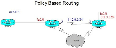
In this scenario the default route for traffic from R2 to R3 is over the frame relay cloud. The requirement here is to policy route ftp traffic originating from R1 1.1.1.1 to R3 3.3.3.3 over the point to point link between R2 and R3

Step 1 - create acl matching traffic

On R2

ip access-list extended 100
permit tcp host 1.1.1.1 host 3.3.3.3 eq ftp
permit tcp host 1.1.1.1 host 3.3.3.3 eq ftp-data

On R3

ip access-list extended 100
permit tcp host 3.3.3.3 eq ftp host 1.1.1.1
permit tcp host 3.3.3.3 eq ftp-data host 1.1.1.1


Step 2 - create route maps


On R2

route-map RICH
match ip address 100
set ip next-hop 11.0.0.3


On R3

route-map RICH
match ip address 100
set ip next-hop 11.0.0.2


Step 3 - apply pbr on incoming router interfaces


On R2 and R3

int fa0/0
ip policy route-map RICH


To verify the routing use the folowing commands

s ip policy

R3#s ip policy
Interface Route mapl
Fa0/0 RICH

To see the policy routing in action

debug ip policy


Sunday, October 5, 2008

BGP Summary Routes

To advertise a summary route within BGP the aggregate-address command can be used. The default is to advertise the summary alongside all the granular routes. The summary-only keyword can be used to change this behaviour, suppressing the granular route advertisement.

There may be lab requirements to vary how summary routes are advertised, for example consider the following scenario

i) advertise the summary 200.1.0.0/16 only to neighbor a
ii) do not advertise the summary 200.1.0.0/16 to neighbor b only the granular routes


This can be achieved as follows

1)
aggregate-address 200.1.0.0 255.255.0.0 summary-only

This will advertise the summary route only to ALL BGP neighbors

2)

ip prefix-list DENYAGG permit 200.1.0.0/16
route-map DENYAGG deny 10
match ip address prefix-list DENYAGG
route-map DENYAGG permit 20

ip prefix-list ALLOW permit 200.1.0.0/17 le 32
route-map ALLOW permit 10
match ip address prefix-list ALLOW

router bgp x
neigbhor b route-map DENYAGG
neighbor b unsuppress-map ALLOW


There are 2 parts to the above solution: first block the advertisement of the summary address and then second use the unsupress-map feature to permit advertisement of the required granular routes.

3550 and 3560 Macros

The tclsh tool is not available on the 3550 and 3560 switches. Instead macros can be used to perform a similar function.

To define the macro in global config

macro name richping
do ping 1.1.1.1
do ping 2.2.2.2
@

To execute the macro

macro global apply richping

To remove the macro when finished.

no macro name richping

Friday, October 3, 2008

RIP - route filtering options


3 ways to filter routes with an even 3rd octet: distribute-list, distance and offset-list

For the distribute-list command I create an acl that matches the routes I want to allow

ip access-list standard 1
permit 0.0.1.0 255.255.254.255


Distribute-list
router rip
distribute-list 1 in


Distance
router rip
distance 255 204.12.5.1 0.0.0.0 1


where 204.12.5.1 is the next hop of the route to be poisioned

For the offset-list commands I create an acl that matches routes I want to block

ip access-list standard 2
permit 0.0.0.0 255.255.254.255


Offset-list
router rip
offset-list 1 in 16

Thursday, October 2, 2008

backup interface

To enable an interface or link as a backup connection make use of the following 2 commands

backup interface x
backup delay a b

where a is the delay in seconds before activating the backup connection and b is the delay in seconds before the prinary interface is re-instated

This configuration is applied to the PRIMARY interface. Verification can be done via the show backup command.

R5#s backup
Primary Interface Secondary Interface Status
----------------- ------------------- ------
Serial2/0.513 Serial2/1 normal operation

Also use the show interface on the secondary/backup interface to display the standby status.

R5#s int s2/1
Serial2/1 is standby mode, line protocol is down

EIGRP part 1 - security


If there is a shared LAN segment and there is a requirement to establish EIGRP adjencies over this but ONLY to specified neighbors, this initially represents a small problem. Of course EIGRP adjacencies are normally established via EIGRP multicast hellos to 224.0.0.10. This is effect allows any router on the LAN segment to join and become an EIGRP neighbor.

By making using of the EIGRP neighbor statement this behaviour can be eliminated. By applying a neighbor statement within EIGRP this stops the multicast hellos from exiting the associated interface. In this way any other hosts on the shared LAN segment are prevented from forming a neighbor adjacency adding a layer of security.

N.B. It is not necessary to apply the passive-interface command to the interface and in fact this will prevent all neighbor relationships forming out of the specified interface.

Wednesday, October 1, 2008

OSPF routing part IV - passive interface

In OSPF the passive interface command behaves a little differently from a distance vector routing protocol like RIP. When applied to an interface it will prevent an OSPF adjacency being formed and hence will not only prevent the sending of updates but receiving of updates also. This effectively creates a 'stub' network.

With RIP the passive-interface command will prevent the sending of updates but will still permit routing updates to be received. To achieve the same functionality within OSPF the command
'ip ospf database-filter all out' can be used.

OSPF routing part III - Authentication


OSPF area 17 is exists between R1 fa0/0 and SW1 fa0/14. In this example i first introduce MD5 authentication and then plain text authentication.

To enable MD5 authentication

Router 1
int fa0/0
ip ospf authentication message-digest
ip ospf message-digest-key 1 md5 CISCO

SW 1
int fa0/14
ip ospf authentication message-digest
ip ospf message-digest-key 1 md5 CISCO


To enable plain text authentication

Router 1
router ospf 1
area 17 authentication
int fa0/0
ip ospf authentication-key CISCO

SW1
router ospf 1
area 17 authentication
int fa0/14
ip ospf authentication-key CISCO


In both cases the verification is to check the neighbor adjanceny is established. Also execute a ‘show ip ospf interface’ to ensure that authentication is denoted as enabled and the authentication type is as expected.
The area x authentication command can be used either at the interface level or the global routing process level. If applied under the global routing process then, as expected, it applies to all interfaces in the specified area. This can be overidden by the interface level command, so allowing different authentication algorithms to co-exist in the same OSPF area.